Basic Principles
A magnetic field is introduced into a specimen to be tested, then fine particles of ferromagnetic powder, or ferromagnetic particles in a liquid suspension, are applied to the area being tested (The “Test Area”). Any discontinuity in the test area which cuts across the magnetic field creates a leakage field. A leakage field has a north and south pole on either side of it, and therefore will attract the ferromagnetic particles in great numbers.
It is common on site work to use black inks as the detecting medium; these are usually contrasted against a white paint background which has been pre-applied. In workshops and similar, it is more common to use fluorescent inks which are usually green/yellow. Fluorescent inks or powders are automatically contrasted against a deep violet background created by the use of an ultraviolet (UV-A) light, this is essential to cause fluorescence of the particles, although the use of a darkened inspection area is required. A contrast paint is not required with fluorescent inks.
Fluorescent inks or powders are more sensitive at detecting defects compared to non-fluorescent inks or powders, because of the greater contrast achieved between the detecting medium and the background.
Sensitivity is controlled by 2 factors, Contrast and Definition. By increasing one or the other the overall sensitivity is increased.
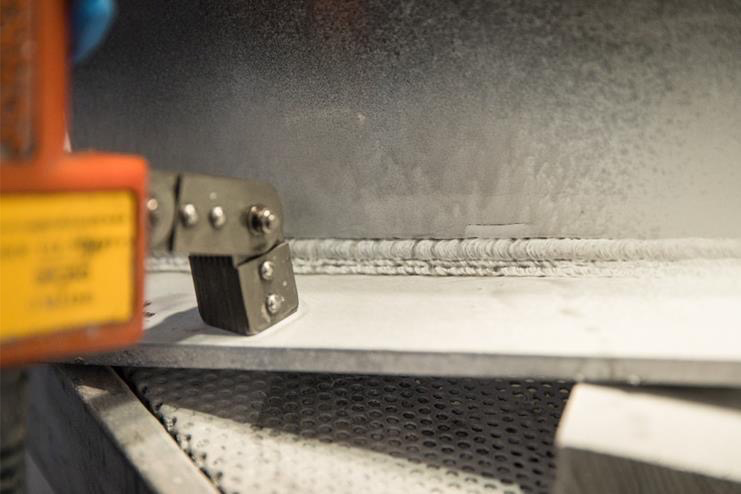
There are many ways to apply a magnetic field, e.g. by the use of permanent magnets, electromagnetic yokes, coils, prods, cables and other devices.
A basic sequence of operations for the examination of a weld using MPI with a permanent magnet and black ink is shown below:
-
Clean area using a wire brush if required and demagnetise.
-
Apply a thin layer of white contrast paint.
-
When the paint is dry, straddle the magnet over the weld at 90° to the weld axis.
-
Apply ink (typically 1.25% to 3.5% ferromagnetic particles to a paraffinbase).
-
Interpret the area. Look for indications with their length lying along the same axis as the weld. Evaluate in accordance with the relevant specification.
-
To look for transverse weld discontinuities, turn magnet approximately 90° and re-apply the ink.
-
Interpret the area. Look for indication with their length perpendicular to the weld axis. Evaluate in accordance with the relevant specification.